Image:Planar core assembly exploded.png
Un article de Wikipédia, l'encyclopédie libre.
Taille de cet aperçu : 800 × 600 pixels
Image en plus haute résolution (1 280 × 960 pixels, taille du fichier : 154 Kio, type MIME : image/png)
| | Ce fichier provient de Wikimedia Commons?. Les informations le concernant sont affichées ci-dessous (procédure). |
[edit] Summary
| Description |
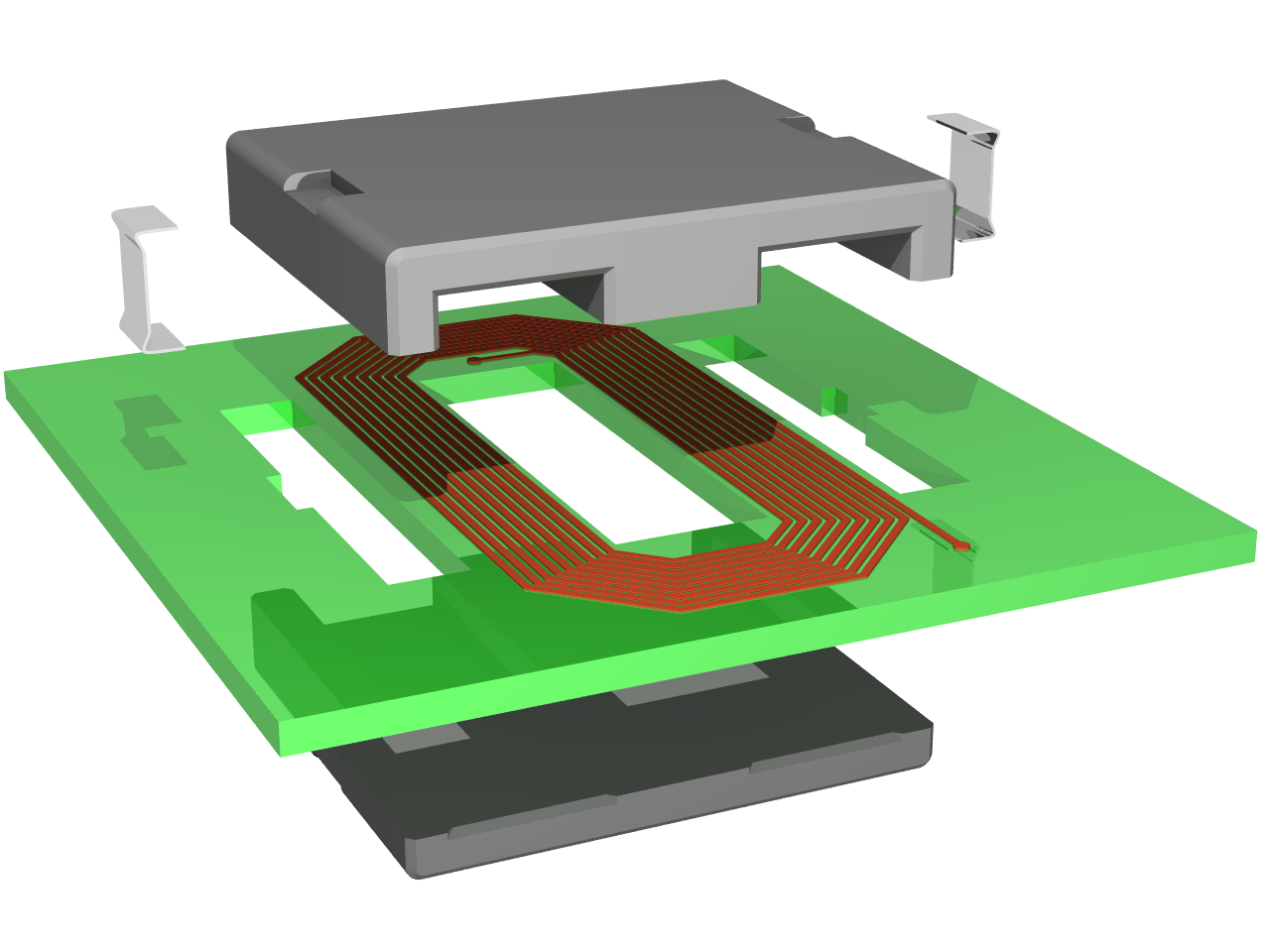
Exploded view of an planar inductor constituted by a spiral track on a printed circuit board and a planar magnetic core |
|---|---|
| Source |
Own work |
| Date |
25/06/2006 |
| Author |
Cyril BUTTAY |
| Permission (Reusing this image) |
as licensed |
| Other versions | Image:Planar core assembly.png |
|
This image has been assessed using the Quality image guidelines and is considered a Quality image. |
[edit] Licensing

Made using povray 3.6 and the following code:
#declare RAD = on;   // use radiosity?
#declare Exploded=on; // exploded view or not?
#declare CoilLength = 2.6;

#include "functions.inc"
#include "metals.inc"
#include "colors.inc"
global_settings {
  #if(RAD)
    radiosity {
      brightness 0.60
      count 100
      error_bound 0.2
      gray_threshold 0.0
      low_error_factor 0.2
      minimum_reuse 0.015
      nearest_count 10
      recursion_limit 1
      #if (version>3.1)
        adc_bailout 0.01
        max_sample -1.0
        media off
        normal off
        always_sample 1
        pretrace_start 0.08
        pretrace_end 0.01
      #end
    }
  #end
}

background { color White }

// declarations for the E magnetic core------------------------------------------------
#declare corner = intersection { // a quarter of cyclindic volume used to "round" the corners
  lathe {
    linear_spline
    6
    <0,0>,<0.05,0>, <0.1,0.05>, <0.1,2.95>,<0.05,3>, <0,3>
    rotate 90*x
  }
  box {<-10,-10,-10>,<10,0,10>}
}

#declare side =  prism { // the extrusions of the volume
  linear_sweep
  linear_spline
  0, 1, 9,
  <0.05,0>, <0,0.05>, <0,2.95>, <0.05,3>, <0.25,3>, <0.3,2.95>, <0.3,0.05>, <0.25,0>, <0.05,0>
}

#declare middle =  prism { // the extrusion of the middle leg
  linear_sweep
  linear_spline
  0, 1, 9,
  <0.05,0>, <0,0.05>, <0,2.95>, <0.05,3>, <0.95,3>, <1,2.95>, <1,0.05>, <0.95,0>, <0.05,0>
}

#declare Ecore = difference {
  union {
    object {side scale <1,3.4,1> rotate -90*z translate <-1.7,0.2,0> }
    object {side scale <1,0.5,1> translate -1.8*x  }
    object {middle scale 0.5*y translate -.5*x  }
    object {side scale <1,0.5,1> translate 1.5*x  }
    object {corner translate -1.7*x}
    object {corner translate 1.7*x}
  }
  union { // the notches where the clips sit
      box {<-10,-10,1.2>,<-1.5,0,1.8>}
      box {<10,-10,1.2>,<1.5,0,1.8>}
  }
  pigment {Gray50}
}

// declarations for the I magnetic core------------------------------------------------
#declare Icore =  difference {
  union {
    object {side scale <1,3.4,1> rotate -90*z translate <-1.7,0.2,0> }
    object {side scale <1,0.2,1> translate -1.8*x  }
    object {middle scale 0.2*y translate -.5*x  }
    object {side scale <1,0.2,1> translate 1.5*x  }
    object {corner translate -1.7*x}
    object {corner translate 1.7*x}
  }
  union { // the notches where the clips sit
      box {<-10,-10,1.2>,<-1.5,0,1.8>}
      box {<10,-10,1.2>,<1.5,0,1.8>}
  }
  pigment {Gray50}
}

//declaration of the coil element-----------------------
#declare coil = union {
  union {
    #declare NbTurns = 8;
    #declare Pitch =0.08; // the distance between two loops
    #declare Xstart =0.6;  // the spiral rolls around the origin
    #declare Zstart =2;
    #declare InitCorner =0.4; // initial lenght of the 45degree filet
    #declare Index=0;
    #declare Width=0.05;
    #declare DeltaL=Pitch*tan(radians(22.5)); //variation in lenght of the track on each turn
    #while(Index <= NbTurns)
      #declare Lengthcorner=InitCorner+2*Index*DeltaL;
      #declare Xlength=2*(Xstart+Index*DeltaL-InitCorner*cos(radians(45)));
      #declare Zlength=2*(Zstart+Index*DeltaL-InitCorner*cos(radians(45)));
      box{<0,0,0>,<-Width,0.01,-Zlength> translate <Xstart+Index*Pitch,0,Zlength/2>}
      box{<0,0,0>,<-Width,0.01,-Lengthcorner> rotate 45*y translate <Xstart+Index*Pitch,0,-Zlength/2>}
      box{<0,0,0>,<-Xlength,0.01,Width> translate <Xlength/2,0,-Zstart-Index*Pitch>}
      box{<0,0,0>,<-Width,0.01,-Lengthcorner> rotate 135*y translate <-Xlength/2,0,-Zstart-Index*Pitch>}
      box{<0,0,0>,<Width,0.01,Zlength+DeltaL> translate <-Xstart-Index*Pitch,0,-Zlength/2>}
      box{<0,0,0>,<-Width,0.01,-Lengthcorner> rotate 225*y translate <-Xstart-Index*Pitch,0,Zlength/2+DeltaL>}
      box{<0,0,0>,<Xlength+Pitch,0.01,-Width> translate <-Xlength/2,0,+Zstart+Index*Pitch+DeltaL>}
      box{<0,0,0>,<-Width,0.01,-Lengthcorner> rotate 315*y translate <Xlength/2+Pitch,0,+Zstart+Index*Pitch+DeltaL>}
      #declare Index = Index + 1;
    #end
    box{<0,0,0>,<-Width,0.01,-Zlength-0.5> translate <Xstart+Index*Pitch,0,Zlength/2>}//connections to the pads
    box{<0,0,0>,<Xstart-InitCorner*cos(radians(45))/2,0.01,-Width> translate <0,0,Zstart-InitCorner*cos(radians(45))/2>}
    box{<0,0,0>,<-Width,0.01,-InitCorner/2> rotate 315*y translate <Xstart-InitCorner*cos(radians(45))/2,0,Zstart-InitCorner*cos(radians(45))/2>}
    pigment { P_Copper4 }
  }
  cylinder{<0,0,0><0,0.015,0>,Width translate <Xstart+Index*Pitch-Width/2,0,-Zlength/2-0.5>}
  cylinder{<0,0,0><0,0.015,0>,Width translate <0,0,Zstart-InitCorner*cos(radians(45))/2-Width/2>}
  pigment { P_Copper4 }
}

//declaration of the pcb------------------------------
#declare PCB = difference {
  box {
    <-3,0,-3>,<3,0.2,3>
  }
  union {
    box {<-0.5,-10,-1.6>,<0.5,10,1.6>}
    box {<-1.9,-10,-1.6>,<-1.4,10,1.6>}
    box {<1.4,-10,-1.6>,<1.9,10,1.6>}
    box {<-2.0,-10,-0.3>,<-1.6,10,0.3>}
    box {<1.6,-10,-0.3>,<2.0,10,0.3>}
  }
  pigment{LimeGreen}
  finish{F_MetalB}
}


//declarations for the clip ---------------------------
#declare halfclip = prism {
  linear_sweep
  bezier_spline
  0, 1, 32, // the following points value come from another model, hence the fancy values
  <0,0>,<1.2,0>,<0,0>,<1.2,0>,
  <1.2,0>,<1.3,0>,<1.6,-0.2>,<1.7,-0.2>,
  <1.7,-0.2>,<1.8,-0.2>,<1.8,-0.2>,<1.8,1>,
  <1.8,1>,<1.9,1>,<1.8,1>,<1.9,1>,
  <1.9,1>,<1.9,-0.3>,<1.9,-0.3>,<1.7,-0.3>,
  <1.7,-0.3>,<1.6,-0.3>,<1.3,-0.1>,<1.2,-0.1>,
  <1.2,-0.1>,<0,-0.1>,<1.2,-0.1>,<0,-0.1>,
  <0,-0.1>,<0,0>,<0,-0.1>,<0,0>
  pigment {P_Chrome1}
  finish {F_MetalD}
}
#declare completeclip = union {
  object{halfclip scale 0.5*y}
  object{halfclip scale 0.5*y rotate 180*z translate 0.5*y}
}

// the final union-------------------------------------------------
union {
  #if(Exploded)
    object {coil translate <0,1.9,1.5>}
    object {PCB translate <0,1.7,1.5>}
    object {completeclip scale <0.7/3.6,1,0.7/3.6> rotate <-90,0,-90> translate <-2.8,3.35,1.75>}
    object {completeclip scale <0.7/3.6,1,0.7/3.6> rotate <90,0,-90> translate <2.8,3.35,1.25>}
    object {Ecore rotate 180*x translate <0,3.7,3>}
  #else
    object {coil translate <0,0.4,1.5>}
    object {PCB translate <0,0.2,1.5>}
    object {completeclip scale <0.7/3.6,1,0.7/3.6> rotate <-90,0,-90> translate <-1.8,0.35,1.75>}
    object {completeclip scale <0.7/3.6,1,0.7/3.6> rotate <90,0,-90> translate <1.8,0.35,1.25>}
    object {Ecore rotate 180*x translate <0,0.7,3>}
  #end
  object {Icore translate <0,0,0>}
  #if(Exploded)
    rotate <0, -30, 0>
  #else
    rotate <0, -40, 0>
  #end
  finish {
    #if(RAD)
     ambient 0
      diffuse 0.7
    #else
      ambient 0.8
      diffuse 0.5
    #end
    phong 1
    phong_size 60
  }
}
light_source { <0, 14, -10> color White}
light_source { <2, 4, -10> color White}
#if(Exploded)
  camera {location <1,8,-15> look_at <-0.3,2.2,0> angle 26}
#else
  camera {location <1,10,-15> look_at <-0.6,1,0> angle 17}
#end
then compiled using the following command:
povray -IPlanar_core_assembly_exploded.png -W1280 -H960 -Q11 +A
Historique du fichier
Cliquer sur une date et une heure pour voir le fichier tel qu’il était à ce moment-là
| Date et heure | Dimensions | Utilisateur | Commentaire | |
|---|---|---|---|---|
| actuel | 24 janvier 2007 à 11:23 | 1 280×960 (154 Kio) | Pngbot | (optimized with optipng) |
| 25 juin 2006 à 15:11 | 1 280×960 (209 Kio) | CyrilB | ({{Information |Description=Exploded view of an planar inductor constituted by a spiral track on a printed circuit board and a planar magnetic core |Source=Own work |Date=25/06/2006 |Author=Cyril BUTTAY |Permission=as licensed |other_versions= }}) |
Pages contenant l’image
Les pages ci-dessous contiennent cette image :

